THE PIEZOELECTRIC
EFFECT
by Graham Woods
Ubiquitous quartz surrounds us - it’s
everywhere, it’s in the soil and in the houses we
live and beats at the heart of almost every piece of
consumer electronics - we're talking crystals here...
Piezoelectricity is the property of quartz
that we utilise in our receiver and transmitter crystals.
So what is it? Put simply: it is an electric voltage
produced by certain crystals and by a number of ceramic
materials when they are subjected to pressure.
What’s more, the piezoelectric effect works both
ways: stress a piece of quartz and you get an electrical
output from it that is proportional to the stress it
undergoes. That is to say, when the quartz has an
electric field applied to it, the crystal becomes
deformed or strained by an amount proportional to the
applied field; the sense of the strain depends on the
direction of the field. Incorporate a crystal in an
oscillator circuit (in our Tx and Rx) and it will make
the circuit run very accurately at the required
frequency.
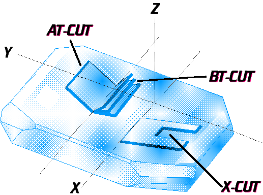 Each
slice of crystal has a natural resonant frequency it
likes to oscillate at depending on the ‘cut’ of
the crystal. The frequency of the crystal is controlled
by the thickness of the quartz slice plus the added metal
electrodes. Most crystals are made from one of three
different cuts (right) of quartz according the frequency
required (Click it for larger image). AT-cut
(1MHz to 300MHz), BT-cut (2MHz to 38MHz fundamental) and
the X-cut (24kHz to 50kHZ). Each
slice of crystal has a natural resonant frequency it
likes to oscillate at depending on the ‘cut’ of
the crystal. The frequency of the crystal is controlled
by the thickness of the quartz slice plus the added metal
electrodes. Most crystals are made from one of three
different cuts (right) of quartz according the frequency
required (Click it for larger image). AT-cut
(1MHz to 300MHz), BT-cut (2MHz to 38MHz fundamental) and
the X-cut (24kHz to 50kHZ).
Of course, there’s much more to it
than that because fundamental frequencies or overtones
are selected for circuits and some oscillators need to be
very temperature stable and so on. In 35MHz R/C equipment
3rd overtone receiver crystals are generally used but
some Tx's like Graupner MC-20 use an 8 point something
MHz fundamental and multiply it up by four.
Designers’ circuitry requirements (single and double
superhet receivers, capacitance, etc) require different
values for receiver crystals too; DS Rx's have two
crystals 10.7 + 24...MHz - this is why crystals are not
interchangeable.
Nowadays, the designers of electronic
equipment don’t go traipsing round the Brazilian
jungle looking for the large natural quartz specimens we
see in museum gemstone collections to cut up; there is a
large business concerned with the growing of manmade
crystals and ceramics of all sorts. The process is hardly
different from that of your school days when you dangled
a seed crystal of copper sulphate on a cotton thread in a
saturated aqueous solution of copper sulphate to grow a
larger specimen. With quartz the process is essentially
the same but uses steel wire suspended in molten quartz
under extremes of pressure and temperature with the
crystal literally pulled slowly from the solution.
Control of the speed of pull, pressure and temperature
and doping agents enables crystal bars of all sorts of
materials from humble quartz to the complex compounds
(for transistors, IC's, l.e.d.'s, etc.) to be created
with precisely aligned crystallographic orientations and
electronic/quantum physical properties. These bars are
then sliced into thin wafers for etching and cutting for
the manufacture of electronic components.
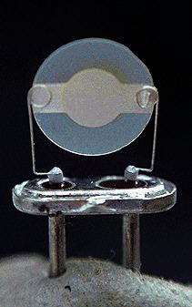 In
my photograph of a damaged 35MHz AT-cut 3rd
overtone receiver crystal (shown here with the
dented can removed) notice how thin the slice of
quartz is; notice too the shaved edge where
quartz slice was aligned with the actual crystal
structure of the crystal when the quartz plates
were cut from the original bar. Now look at the
those hair-thick wires with loops on... your
prized or expensive model is hanging on just such
a pair of delicate wires inside the receiver!
Remember this the next time you crash a model.
Also note that pulling crystals in and out of
equipment doesn't do the crystal pins and sockets
any good at all - these delicate, sensitive
wafers of quartz are hermetically sealed in a dry
nitrogen atmosphere in their cans with their pins
in 'glass' seals and should be handled with care
so as not to damage the seal. If the seal fails
then moisture can penetrate the can and degrade
the electrodes. It goes without saying you should
take special care of your crystals. In
my photograph of a damaged 35MHz AT-cut 3rd
overtone receiver crystal (shown here with the
dented can removed) notice how thin the slice of
quartz is; notice too the shaved edge where
quartz slice was aligned with the actual crystal
structure of the crystal when the quartz plates
were cut from the original bar. Now look at the
those hair-thick wires with loops on... your
prized or expensive model is hanging on just such
a pair of delicate wires inside the receiver!
Remember this the next time you crash a model.
Also note that pulling crystals in and out of
equipment doesn't do the crystal pins and sockets
any good at all - these delicate, sensitive
wafers of quartz are hermetically sealed in a dry
nitrogen atmosphere in their cans with their pins
in 'glass' seals and should be handled with care
so as not to damage the seal. If the seal fails
then moisture can penetrate the can and degrade
the electrodes. It goes without saying you should
take special care of your crystals. Once
a wafer has been cut, the next stage of the
production process involves the reduction in
thickness of the quartz to get it to the correct
size - this skilled process is called 'lapping'.
During this stage the sliver of quartz is
'lapped' to the correct size so it will resonate
at the correct frequency. Some say this process
is somewhat of a 'black art'. Electrodes of
silver or gold are added by vacuum deposition -
this is where the wires are connected. The final
frequency of the crystal is adjusted by adding an
extra layer of silver to one side of the quartz
sliver. Tolerances are extremely fine (measured
in parts per million) and define how close the
resonant frequency is to the required frequency -
the smaller the tolerance the more expensive it
will be. Crystal frequency is usually specified
at 25ºC since crystal accuracy is very
temperature dependent - some crystals are made to
operate in temperature controlled ovens.
|
The Piezoelectric Effect was discovered in
the 1880's and is used widely in a number of transducers
and electronic gear. Your old record player had a
cartridge that used the piezoelectric effect, the
ultrasonic transducers in your ancient car alarm used it,
that hospital ultrasound scanner uses it, some gas and
cigarette lighters use it. Then there are strain gauges
and accelerometers, flow meters and pressure transducers
of all sorts including altimeters, variometers and
airspeed indicators not forgetting modern barometers,
model gyros, radios, TV’s, microphones and
computers, your Swatch watch and even artificial limbs.
You name it, there's a tiny piece of quartz or
piezo-ceramic in there somewhere.
As an aside: on a global scale, large
earthquake movements are also said to produce
massive releases of piezoelectricity in the form of
sparks and ball lightning as rock formations are put
under extremes of pressure.
THE UK 35 MHz R/C BAND
|
CHANNEL NUMBER
|
TRANSMITTER FREQUENCY
|
RECEIVER FREQUENCY
|
Frequencies
in red are the newer channels released for use in late 2000.
They may not be universally available for a while. These
new frequencies should not be confused with the German B-band
in 35MHz.
35 MHz is
the preferred frequency band for model flying in
the UK. 27 MHz 'solids' can be used but this band
is not recommended for flying models. In the
table there is a list of regular (non DS) 35 MHz channel numbers
and their matching transmitter and receiver
frequencies. Certain types of equipment
(Multiplex, Futaba FC series, etc.) actually use
a lower frequency crystal in the transmitter, and
use a doubler circuit, so you may find that you
have a transmitter crystal that actually reads
half that shown here (e.g. 17.575 MHz instead of
35.150 MHz for channel 75).
Receiver crystal
frequencies are different since the internal
intermediate frequency (I.F.) into account. This
is 455 kHz for standard receivers nowadays.
Double superhet (DS) receivers use a second 10.6
MHz I.F. as well as the 455 kHz I.F. (some of these
crystals may well read 10.7 MHz lower than
those shown in the table. Not all crystals can be
used in all radio sets and receivers - you must
check for yourself.
Frequencies in
red are the new channels released for use in late 2000. They may
not be universally available for a while. These new frequencies
should not be confused with the German B-band in 35MHz.
|
55
56
57
58
59
60
61
62
63
64
65
66
67
68
69
70
71
72
73
74
75
76
77
78
79
80
81
82
83
84
85
86
87
88
89
90
|
34.950
34.960
34.970
34.980
34.990
35.000
35.010
35.020
35.030
35.040
35.050
35.060
35.070
35.080
35.090
35.100
35.110
35.120
35.130
35.140
35.150
35.160
35.170
35.180
35.190
35.200
35.210
35.220
35.230
35.240
35.250
35.260
35.270
35.280
35.290
35.300
|
34.495
34.505
34.515
34.525
34.535
34.545
34.555
34.565
34.575
34.585
34.595
34.605
34.615
34.625
34.635
34.645
34.655
34.665
34.675
34.685
34.695
34.705
34.715
34.725
34.735
34.745
34.755
34.765
34.775
34.785
34.795
34.805
34.815
34.825
34.835
34.845
|
|